| Interactive Swarm Space | |||||||||||
|
|
||||||||||||||||||||||||||||||
|
Filters and Resonators Table of Contents BWFilter Unit (Butterworth) The Butterworth Filter has the following characteristics: a flat frequency response in the passband, a linear rollout in the reject band. The filter's order defines the steepness of this rollout: first order = 6 db/octave, second order = 12 db/octave, third order = 18 db/octave and so on. However until today, only the second order filter is implemented. There are four filter types which are described in the next section: lowpass, highpass, bandpass and bandreject (or bandstop) Default constructor: BWFilter() This will give you a standard 2nd order lowpass filter (type = BW_LOWPASS). Default constructor with filter type argument: BWFilter(FILTERTYPE) This will give you a standard 2nd order filter with one of the following types. There are 4 types of filters for this unit: BW_LOWPASS, BW_HIGHPASS, BW_BANDPASS, BW_BANDSTOP. For instance if you need a bandpass filter, simply write: BWFilter f = new BWFilter(BW_BANDPASS); PortsControl Ports
frequency: When using a lowpass/highpass filter this control port is the cutoff frequency. For bandpass/bandreject filters it is the center of the frequency band ("bandWidth" * 2). bandWidth: Only bandpass and bandreject filters make use of this control port value. As for the practical value of this control parameter, you need to keep in mind that the bandwidth does not actual state the frequency band outside of which (or inside in case of the bandstop filter) the frequency response equals zero. Since there is a smooth transition region in the frequency response where band-filtering takes place, the edge of this band is defined as the frequency at which the frequency response drops below -3 db (half the amplitude of the original sound). As a rule of thump, double your "bandWidth" value and you'll get a more practical value. 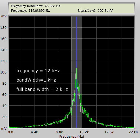 bandpass filter with a 2 kHz band Example SyntaxSimple Lowpass Example Noise* whiteNoise = new Noise(); //some white noise as example input audio to the filter
BWFilter* lpFilter = new BWFilter();
lpFilter->set("frequency", 500.0);
whiteNoise->connect(lpFilter);
lpFilter->connect(outputUnit);
Bandpass Filter Sweep Noise* noise = new Noise();
BWFilter* bpFilter = new BWFilter(BW_BANDPASS);
bpFilter->set("frequency", 10.0); //start frequency
bpFilter->set("bandWidth", 50.0);
noise->connect(bpFilter);
bpFilter->connect(outputUnit);
// event parameters
int startTime = 1000; //start the sweep after 1 sec
float targetFrequency = 12000.0; //sweep ends at 12000 Hz
int duration = 10000; //sweep duration: 10 secs
// create the event (the linear frequency sweep)
Synth::get().eventManager().createEvent(startTime,
bpFilter->controlPort("frequency"),
targetFrequency, duration);
Please refer to chapter "Events" for further details about events Known Issues:implement nth-order parameterizable filter (until now it's only 2nd order) A RESON Filter is a general-purpose filter that exhibits a single peak. The frequency response of a RESON filter is nowhere near as flat as a Butterworth filter frequency response. Nevertheless, all typical equalizer implementations typically implement classic reson filters. This digital filter type has several problems, most of which cannot be explained here. Here is a short overview of the most common problems.
Q = frequency / bandWidth or bandWidth = frequency / Q If you work with moving poles of a reson filter, we recommend you scale the bandwidth according to the changing center frequency accordingly. PortsControl Ports
bandWidth: see introductory comments on the RESON bandwidth at the beginning of this unit's description Example Syntax1-pole reson filter example
Noise* noise = new Noise();
ResonFilter* resonFilter = new ResonFilter();

resonFilter->set("frequency", 400.0);
resonFilter->set("bandWidth", 50.0);

noise->connect(resonFilter);
resonFilter->connect(outputUnit);
3-pole reson filter
Noise* noise = new Noise();
ResonFilter* resonFilterLow = new ResonFilter();
ResonFilter* resonFilterMid = new ResonFilter();
ResonFilter* resonFilterHigh = new ResonFilter();

resonFilterLow->set("frequency", 100.0);
resonFilterLow->set("bandWidth", 10.0); // Q = 10
resonFilterMid->set("frequency", 500.0);
resonFilterMid->set("bandWidth", 250.0); // Q = 2
resonFilterHigh->set("frequency", 1000.0);
resonFilterHigh->set("bandWidth", 200.0); //Q = 5

noise->connect(resonFilterLow); //signal splits into 3 branches
noise->connect(resonFilterMid); //branch 2
noise->connect(resonFilterHigh); //branch 3
resonFilterLow->connect(outputUnit); //mixdown
resonFilterMid->connect(outputUnit);
resonFilterHigh->connect(outputUnit);
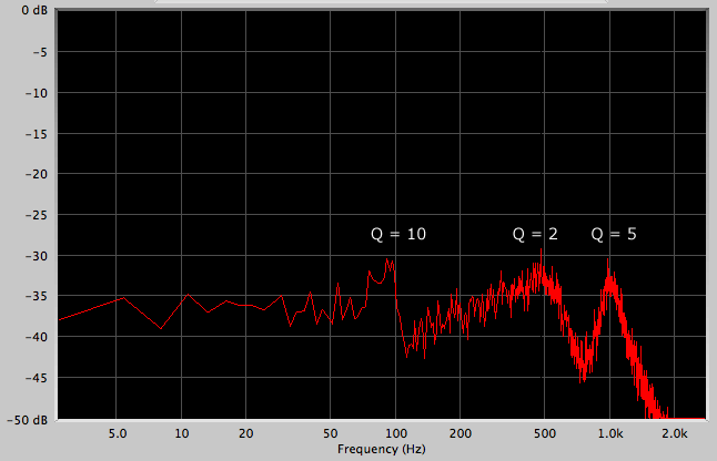 3-pole reson filtered noise Known Issues:gain? negative gain - experiment with inverse filtering and document experiences? Q = frequency / bandWidth, might be a better value than the actual bandWidth. Ask Beat: what is the phase response of a reson filter, is there a danger of phase cancellation when I do my 3-pole example? Would a allpass filter do the trick? The CombFilter unit is an implementation of the discrete-time feedback comb filter. The available control parameters are: delay, gain and feedback. These are described in the according control port section further bellow. The frequency response of a feedback comb filter generally looks like the teeth of a comb. 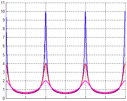 frequency response of a feedback comb filter The delay control value controls the width of the intervals between the teeth. If you intend to use the comb filter in a musical way, e.g. to filter out certain harmonic spectra relative to a basic frequency, there is a simple way to transform frequency into delay time: delay_time = 1000.0 / frequency You are advised to define the maximal delay time by the according constructor parameter in order to allocate a delay buffer big enough for your needs. Should your "delay" control value ever exceed the maxdelay your program is likely to crash due to buffer overflow. An example: CombFilter* f = new CombFilter(2000.0); //maximum delay of 2 secs
f->set("delay", 2001.0); //crash!!
PortsControl Ports
delay: gain: feedback: Example SyntaxNoise* noise = new Noise();
CombFilter* combFilter = new CombFilter(23.0);
combFilter->set("delay", 2.3);
combFilter->set("gain", 0.8);
combFilter->set("feedback", 0.9);
noise->connect(combFilter);
combFilter->connect(outputUnit);
Known Issues:Where is feedforward? experiment with different values for delay, gain, feedback, what happens when delay>maxdelay? leaving d/g/f the same does changing maxdelay alter the sound? - yes, bug!!! FSMFilter Unit (Frequency Sampling Method) The frequency sampling method filter type lets you specify a spectral envelope by passing a list of evenly spaced odd-numbered amplitude samples to the filter (sampled envelope). The filter algorithm itself will then try and approximate this envelope and create a set of internal filter coefficients. Since it is a non-recursive filter (a.k.a. finite impulse response filter), it has a linear phase response - meaning only each frequency's amplitude (or amplitude response) is altered by the filter, the phase is left intact for all frequencies. A FSM filter works best for envelopes without any abrupt changes (as for example a very steep lowpass filter). Such drastic changes will create artifacts on either side of the discontinuity. However by raising the number of samples in the envelope in a manner that one sample lies somewhere in the transition of the discontinuity, these artifacts can be reduced. The approximation is exact in these sampled points and smoothly interpolates in between them in a spline-like manner. Therefore, the less sampled values your envelope holds, the more continuous the resulting amplitude response will be, but the less accurate (and vice versa). The value list describing the formant or spectral envelope can be supplied in two ways: Either by calling the constructor together with a vector of samples (this is mandatory when creating an FSMFilter unit object) or by passing a new Frame object to the method setEnvelope(). This filter unit has no control ports, so you must explicitly call setEnvelope() to change the envelope. This filter is best suited for situations where you need linear phase responses and/or rely on a filter to process a fairly complex frequency envelope - in other words: a formant. For more information about non-recursive filters and the frequency sampling method, please refer to "Computer Music: Synthesis, Composition, and Performance " by Charles Dodge and Thomas A. Jersey. Setting the envelope on initialization: Code here... Changing the envelope at runtime: Code here Switch Ports
envelope: describe here... Example SyntaxExample Syntax here Known Issues:How to create an envelope, both cases... See Dodge! What about that switchport? VocalFormantFilter uses a series of 5 butterworth band filters to emulate the human vocal tract forming the 5 basic vowels 'a', 'e', 'i', 'o' and 'u'. The unit holds a ControlPort for each of the vowels, making it possible create transitions between vowels. Courtesy of Bennett/Rodet's "Synthesis of the Singing Voice" (1989). PortsControl Ports
Example SyntaxThis example uses five sinewave modulators to operate the ControlPorts for 'a','e','i','o','u'. A pink noise unit is the the carrier for the vocal filter. More natural results can be achieved by feeding it a cyclic bandlimited impulse ("buzzer"). PinkNoise* noise = new PinkNoise();
WaveTableOscil* mod_A = new WaveTableOscil("sinewave");
WaveTableOscil* mod_E = new WaveTableOscil("sinewave");
WaveTableOscil* mod_I = new WaveTableOscil("sinewave");
WaveTableOscil* mod_O = new WaveTableOscil("sinewave");
WaveTableOscil* mod_U = new WaveTableOscil("sinewave");
VocalFormantFilter* filter = new VocalFormantFilter();
mod_A->set("frequency", 0.1);
mod_E->set("frequency", 0.22);
mod_I->set("frequency", 0.39);
mod_O->set("frequency", 0.41);
mod_U->set("frequency", 0.59);
mod_A->set("amplitude", 0.5);
mod_E->set("amplitude", 0.5);
mod_I->set("amplitude", 0.5);
mod_O->set("amplitude", 0.5);
mod_U->set("amplitude", 0.5);
mod_A->set("offset", 0.5);
mod_E->set("offset", 0.5);
mod_I->set("offset", 0.5);
mod_O->set("offset", 0.5);
mod_U->set("offset", 0.5);
filter->set("bandWidthExp", 0.5);
noise->connect(filter);
mod_A->connect(filter, "a");
mod_E->connect(filter, "e");
mod_I->connect(filter, "i");
mod_O->connect(filter, "o");
mod_U->connect(filter, "u");
filter->connect(outputUnit);
|
| Last updated: May 15, 2024 |