| Interactive Swarm Space | |||||||||||
|
|
||||||||||||||||||||||||||||||||||||||||||||
|
Basic Synthesis Techniques Table of Contents Introduction This section is not an attempt to give you an introduction to sound synthesis techniques since there is plenty of literature available on this matter, some of which is mentioned in the reference section at the end of this tutorial. However we will give you guidance in how to implement the most common sound synthesis techniques with ISOSynth. Of course we encourage you to expand the ideas presented here and experiment with your own approaches to sound synthesis. Steady-State Additive SynthesisThe following example shows a steady-state oscillator bank with a harmonic spectrum. The amplitude of each partitial (harmonic or overtone) is set randomly between 0.0 and 1.0 (the default range for the math.uniformRandom() method). As with all methods from the core math library, you need to import it first using this instruction: core::Math& math = core::Math::get(); //fetch math object, we'll need it for uniformRandom() int number_of_partitials = 12; Time-varying Additive SynthesisThere are a couple of methods for controlling the amplitudes of each oscillator.
Early experiments with additive synthesis have shown that it is in fact possible to create natural sounding results with mathematical approaches, however the effort is overwhelmingly higher than the use of control data derived by analysis of an existing natural sound. Still a great deal of interesting sounds can be generated by purely mathematical generation of progressions, e.g. by using LFO oscillators. Unlike other synthesis libraries, ISOSynth does not make a distinction between audio-time data and control-time data (aka a-rate/k-rate). Everything is in audio time, so you can use the same oscillator class (WaveTableOscil) to create an LFO as you are when creating an audible oscillator. These data sets can either be stored in an array, a vector, a wavetable or a function generator. Of course you might want to interpolate between these function points, in which case you can select among the following approaches:
int number_of_partitials = 12; A final note on additive synthesis: You might have noticed, we merely scratch on the surface of additive synthesis here. Please consult any of the computer music tutorial literature listed in the reference section to gain further insight In the following example we will send noise through a 3rd-order butterworth lowpass filter. This 3rd order is achieved by daisy-chaining three first-order filters. With each order, the steepness of the filter increases by 6 db/octave. The following example will produce a 18 db/octave lowpass filter. Noise* noise = new Noise();
BWFilter* filter = new BWFilter(BW_LOWPASS);
BWFilter* filter2 = new BWFilter(BW_LOWPASS);
BWFilter* filter3 = new BWFilter(BW_LOWPASS);
filter->set("frequency", 100.0);
filter2->set("frequency", 100.0); //2nd order
filter3->set("frequency", 100.0); //3rd order
noise->connect(filter); //serial alignment of filters! input->1; 1->2; 2->3; 3->output
filter->connect(filter2);
filter2->connect(filter3);
filter3->connect(m_output);
Butterworth filters do not have a resonance parameter. Probably the easiest way to do this is to add an extra bandpass butterworth filter or alternatively a reson filter. If you decide to implement such a resonant filter, it's advisable to control the frequency response of your patch by a sinewave sweep. Distortion synthesis refers to a class of computationally efficient synthesis methods that were developed in the early days of computer music. Surely the most popular member of this family of synthesis techniques is John Chowning's FM synthesis, but there is also nonlinear waveshaping, amplitude modulation and ring modulation. There are loads of books available on the theory behind these techniques - please refer to our Reference section for a small selection of books and online links. At this point we believe, it is quite sufficient just to supply you with some code examples that give you the necessary insight into the world of nonlinear synthesis and therefore a head start to develop your own patches. First, we will start with an implementation of time-varying Frequency Modulation. The following code will produce a steady state spectrum of a clarinet-like sound (as described by Jean-Claude Risset). You could modify this example by driving it with two envelopes, one for the amplitude of the carrier and one to control the spectrum (amplitude of the modulator). Notice how we set the offset parameter of the modulator to 900.0 Hz. This serves the purpose to avoid adding an extra unit (AddUnit) who's purpose would be to add the carriers frequency (900 Hz) and the Modulators output together. WaveTableOscil* carrier = new WaveTableOscil("sinewave");
WaveTableOscil* modulator = new WaveTableOscil("sinewave");
modulator->set("frequency", 600.0);
modulator->set("offset", 900.0);
modulator->set("amplitude", 200.0);
modulator->connect(carrier, "frequency"); //"Frequency Modulation"
carrier->connect(m_output);
The following simple example will modulate the carrier's amplitude - a technique which is accordingly called Amplitude Modulation. WaveTableOscil* carrier = new WaveTableOscil("sinewave");
WaveTableOscil* modulator = new WaveTableOscil("sinewave");
carrier->set("frequency", 900.0);
modulator->set("frequency", 600.0);
modulator->connect(carrier, "amplitude"); //"Amplitude Modulation"
carrier->connect(m_output);
Next, a short code sample will demonstrate the implementation of a simple Ring Modulation patch: WaveTableOscil* osc1 = new WaveTableOscil("sinewave");
WaveTableOscil* osc2 = new WaveTableOscil("sinewave");
MultiplyUnit* ring = new MultiplyUnit();
osc1->set("frequency", 30.0);
osc2->set("frequency", 201.0);
And last , we will show you how to create your own wavetable in order to create your own transfer function for Wavetable Synthesis. (TODO, Daniel is working on this right now...) This unit converts any audio signal it receives at its audio input port in a trail of grains. Grains are triggered by pulses received at the trigger control port. This unit has extensive configuration capabilities. The grain envelope is controlled by a pointlist. The setEnvelope function allows to define new envelopes. There exist control ports for the amplitude of grains, the grain duration, the delay (in millisecs) of grains (grain read their audio data from a ring buffer), and the play back rate of grains. The playback rate of grains can be positive or negative and doesn't affect the grains envelope duration. Furthermore, the grain delay may automatically be adjusted to take the start position of a grain within a audio buffer into account. This option is essential to recreate the original audio input with sample accuracy (for example for pitch shifting effects). There is also an option to compensate for amplitude variations due to the number of grains and envelope shape.This option produces only reasonable effects if the grain density is high (i.e. all grains overlap). It shouldn't be active when some grains are non overlapping. Finally, whenever the playback rate of grains is not 1.0, there is an option to create the grain's audio signal via interpolation. Until today, there are two units available that can supply GranularUnit with trigger data: PulseUnit and RhythmUnit
PortsControl Ports
trigger: This control port is used to receiver trigger pulses. A grain will be triggered if these two conditions are met: The current signal has a non-zero value and the previous signal value (t-1) was zero. This avoids that continuous non-zero input data triggers a new grain every sample. amplitude: Amplitude of each grain. Please look at the SwitchPort "amplitudeCompensation" duration: Duration rate of the grain. Norm is 1.0, so 2.0 would mean twice and 0.5 half the duration time and so on. delay: Absolute delay time in milliseconds. playRate: speed at which the sample material is fed through the grains. Negative play rates will inverse playback. Switch Ports
grainCount: max number of grains that can be active simultaneously. Remember that grains are triggered by the "trigger" ControlPort. Setting a max number of simultaneous grains will avoid the CPU being exhausted by a great number of overlapping grains. delayCompensation: adapt grain delay values depending on their trigger position within a audio buffer. This is essential for creating perfectly aligned grain buffers that recreate the original audio signal. Turn this option on if you would like to use granular synthesis for pitch shifting effects. Takes only the value stored at channel 0 into account. amplitudeCompensation: normalize sample amplitudes based on grain envelopes. interpolation: turn on or off subsample interpolation. Subsample interpolation has only an effect for play rates != 1.0 IntroductionWhile FFT is a very promising technique in sound analysis and synthesis, it is also one of the processes that are not quite as easy to wrap one's head around. Luckily we have encapsulated the actual FFT and iFFT action in such a way, that you will be able to use it in your patches with minimal knowledge. What's FFT?FFT (fast fourier transform) is an immensely successful technique of translating a signal from the amplitude domain (amplitude as a function of time) to the frequency domain, iFFT on the other hand does the exact opposite. While our own ear is excellent at doing this computation (i.e. hearing specific frequencies, following melodic lines, etc.) it's actually a very tough problem and one that many scientist have tried to find computationally inexpensive solutions for. Why is it interesting to have spectral information about a signal, you might ask. Well for one thing, there's a bunch of cool stuff you can accomplish, if you have this spectral information, you can for example alter the pitch without affecting playback speed (pitch shift), or you can stretch, suppress, deform and selectively cancel out certain spectral parts. FFT has some limits though, for one, it's a windowed process, that assumes, the signal inside each window (time lapse) is periodic. Reassembling these windows with iFFT back to a waveform can in some cases produce considerable artifacts (yay!). Most of these artifacts can be avoided be cleverly choosing FFT parameters. There are about a zillion tutorial on the net or in the books in our Reference section concerned with FFT, so there is no point in getting deeper into that here. How to use FFT in ISO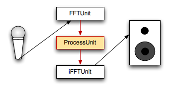
ISO FFT data flow This is a simplified architectural overview of an FFT patch. An input signal is fed to the FFTUnit and from there output as two separate channels, one holding the frequency information, and the other one holding the phase information. These two channels are being manipulated by an intermediate ProcessUnit and then fed to an iFFTUnit which translates the two channels. The ProcessUnit could be any subclass of ProcessUnit, but since we are NOT dealing with normal audio buffers, but with spectral data (red arrows), there are only a certain set of ProcessUnits that will create meaningful results:
We encourage you to write your own spectral transformation unit! Overlap and WindowsOverlapping can help FFT to get a smoother sound output (i.e. less noise artifacts). However, overlaps put a huge strain on the unit, because the internal sampling rate doubles with each overlap increase of one. You don't need to be concerned with the higher sampling rate, just remember, big overlaps are expensive!! overlap of 1 -> original sampling rate (SR) Here is how you set an overlap: When initializing your object, use a constructor that lets you specify the overlap. For example this one: FFTUnit* fft_w_overlap = FFTUnit(FunctionType pWindowType, unsigned int pOverlap); Try to start without an overlap (default, overlap = 1) then raise the value step by step while keeping one eye on your CPU performance monitor. And finally, you have to know about windowing. A window function is like an envelope that starts and ends with 0.0 amplitude. This is to assure that all windows' waveforms can be smoothly cycled and those periodic signals, that's what FFT will look for. However in applying such an envelope, you of course interfere with the signal itself. For that reason, there are several window functions to choose from:
More on spectral windows can be found here: Example CodeThe following code will feed the FFT'd signal through a FFTAmpScale ProcessUnit. A Hamming window is applied along with an overlap of 3 unsigned int windowOverlap = 3;
unsigned int frameCount = 1024;
unsigned int channelCount = 1;
SampleUnit* sampleUnit = new SampleUnit("myFreakySourceSignal.aif");
FFTUnit* fftUnit = new FFTUnit( HAMMING, windowOverlap, frameCount,
channelCount, Synth::get().defaultRate() );
FFTAmpScale* fftAmpScale = new FFTAmpScale( windowOverlap, frameCount,
channelCount, Synth::get().defaultRate() );
IFFTUnit* ifftUnit = new IFFTUnit( windowOverlap, frameCount, channelCount,
Synth::get().defaultRate() );
fftAmpScale->set("ampScale", 1.2);
sampleUnit->connect(fftUnit);
fftUnit->connect(fftAmpScale);
fftAmpScale->connect(ifftUnit);
ifftUnit->connect(outputUnit);
|
| Last updated: May 15, 2024 |