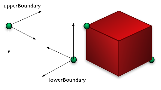
MIN_BOUNDS and MAX_BOUNDS
Table of content:
When is it necessary to use messages?
How to set up a sender and receiver for ISOFlock
Setting up a sender for ISOSynth
Sending/Receiving OSC control messages with Max/MSP
Sending/Receiving OSC control messages with Python
Since ISOFlock and ISOSynth (and ISOTracker for that matter) are independent applications, the question of intercommunication has soon become apparent in order to enable communication between the two engines. We have chosen a network communication approach for his, regardless of whether your ISO engines are running on one computer or are spread across multiple machines (see comment box bellow on distribution of ISO components).
Apart from ISO-to-ISO communication, there are a lot of other possibilities thanks to the recent introduction of OSC messaging, we'd like to mention a few of those here:
| In which situations should you use multiple computers: Even with today's processing power, it's not a difficult task to create swarms that put a strain on your processor(s) - likewise if you attempt to use FFT-based sound synthesis, complex filtering, or simply a whole bunch of ISOSynth units of any kind really, you will eventually run out of processing power, which can be heard as drop-outs in your output audio. Flocks on the other hand don't show the same same skipping reaction when they hit the CPU limit, but rather get slower, because flock simulations are calculated step by step. Thus for complex projects we highly recommend using separate computers for ISOFlock and ISOSynth. What do we mean by complex - that's of course not so easy to define, but for simplicity's sake we'd say a swarm is complex above an agent count of 500 to 1000, depending on the chosen neighborhood algorithm. If for some reason you need a lot more agents, one possibility would be to distribute the swarm itself on different machines - this will however create a slightly different simulation outcome due to the network lag introduced by the swarms not residing on the same computer. |
Most of you will only want to know how setup senders and receivers and don't have to know about messages structures and parsers and so on. So let's dive in right ahead.
Simply insert the following line of code bellow Simulation::init(1.0);
simulation.com().createReceiver(RECEIVER_NAME_STRING, LISTENER_PORT_INT, PROTOCOL_TYPE, FORMAT_TYPE);for example
simulation.com().createReceiver("FlockReceiver", 7500, com::UDP, com::DEFAULT);
which will create a receiver called FlockReceiver, that's listening for UDP messages on port 7500 and has the ISO-standard format, which is optimized for all ISO-to-ISO communication.
PROTOCOL_TYPE can be com::UDP or com::TCP.
FORMAT_TYPE can be com::DEFAULT or alternatively com::OSC (but more on that later).
simulation.com().createSender( SENDER_NAME_STRING, LISTENER_PORT_INT, PROTOCOL_TYPE, FORMAT_TYPE );
After you have set up your swarms and behaviors, insert the following line of code in order to enable for sending a specific parameter:
simulation.com().registerParameter( SENDER_NAME_STRING, SWARM_NAME_STRING, PARAM_NAME_STRING );
for example:
simulation.com().registerParameter( "FlockSender", "myswarm", "position" );
That's the most basic form of registering a parameter. You have some options though. You can define parameter value limits for example, by specifying two limiting vectors the same way we have implemented motion boundaries in our Hello World example:
simulation.com().registerParameter( "FlockSender", "myswarm", "position",
    math::Vector<float>(3, -5.0, -5.0, -5.0), math::Vector<float>(3, 5.0, 5.0, 5.0) );
MIN_BOUNDS and MAX_BOUNDS
MIN_BOUNDS and MAX_BOUNDS have to be a "math::Vector<real>&" vector or a subclass of it. In our example above, since position has three dimensions, we are using math::Vector3<float> (in ISOFlock "real" is just a typedef on float). If you would like to track one-dimensional parameters however, you would use the math::Vector<float>. These bounds are to be interpreted as follows: The position of an agent in is truncated, meaning if, say, the current xyz-position is (1.3, 2.8, 5.5) it will be truncated down to (1.3, 2.8, 5.0). However, an this is very important, this bounds are also used to normalize agent positions in the range between 0 and 1! So all message values are only within the range of 0 and 1! Look out for that.
On the synth side it's a little more verbose. Let's start by looking at a rather simple example: We would like our 50-agent flock to control the amplitudes and frequencies of 50 oscilators inside an additive synthesis patch. We assume you have followed the instructions in "Setting up a sender for ISOFlock".
So you have your synthesis patch (in our example AdditiveSynthesisPatch.h and .cpp) and as usual, you use your main() method in the iso_synth_app project to create an instance of your AdditiveSynthesisPatch class. Consequently it is your main() method, where you need to take care of setting up and linking a message receiver to your patch:
int main( int argc, char **argv )
{
	Synth& synth = Synth::get();

	try
	{
		QApplication a(argc,argv);

		synth.com().createReceiver("FlockReceiver", 7500, com::UDP, com::Default );

		AdditiveSynthesisPatch* patch = new AdditiveSynthesisPatch(10, 440.0);
		OutputUnit* outputUnit = new JackOutputUnit( 2, "system" );
		patch->unit("AdditiveSynthesisPatch_out")->connect(outputUnit, new ChannelMap(2, 1, 1) );
		Synth::get().com().registerMessageListener( "FlockReceiver", *patch );

		Synth::get().start();
		sleep(700000);
		Synth::get().stop();
		Synth::destroy();

		return a.exec();

	}
	catch(base::Exception& e)
	{
		Synth::get().exceptionReport(e);
	}

    return 0;
}
Let's look closely at the code fragements in bold:
//Get synth singleton and create a receiver called "Flock Receiver" on port 7500,
//using the UDP protocol and the default ISO message format:
synth.com().createReceiver("FlockReceiver", 7500, com::UDP, com::Default );

//create an instance of your patch:
AdditiveSynthesisPatch* patch = new AdditiveSynthesisPatch(10, 440.0);

//create an audio output object with two channels (stereo):
OutputUnit* outputUnit = new JackOutputUnit( 2, "system" );

//connect your patch's mono output to the two inputs of your output object:
patch->unit("AdditiveSynthesisPatch_out")->connect(outputUnit, new ChannelMap(2, 1, 1) );

//assign (or register) the message listener to your patch
//(side-note: patch is a pointer, so "*pointer" de-references it)
Synth::get().com().registerMessageListener( "FlockReceiver", *patch );
Now what's left is to define how the data in a message is used to control the synth units in your patch. This is defined in your patch's notify() method. Until now, the actual dissection of the message and applying the collected data to your units is somewhat tedious since you have to know the message structure in order to pick out the right kind of data from the stream. Because of that, here's a quick overview over the standard message structure:
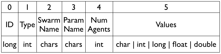
ISO message protocol
| Value Group | Description |
|---|---|
| ID | sequencial message number |
| Type | (not used currently, but could serve es message diversificator) |
| Swarm Name | name of sending swarm |
| Param Name | name of swarm's parameter |
| Num Agents | number of sending agents |
| Parameter Values | block of actual parameter values, can be chars, ints, longs, floats or doubles. |
This is the format in which the message is sent to your patch's notify() method. You can see that there are 6 value groups, but only the last one contains the actual message data, the ones before however will help you in decomposing it. And here's how it's done:
//inside your patch's cpp file:

void

AdditiveSynthesisPatch::notify(const com::Message& pMessage)

{

	if(mActive == false) return; //if patch is inactive, ignoring message


	try

	{
        // a message has always 6 value groups:
        if(pMessage.valueGroupCount() < 6) return;
        // skip if already received:

        if( mPreviousMessageId == ( pMessage.values<long>(0) )[0] ) return;

        // copy reference to local object:

        com::Message message = pMessage;


        // get num of agents by reading value group 4 ("Num Agents"):
        int parCount = ( message.values<int>(4) )[0];
        // get "Parameter Values" as float array:
        const float* parValues = message.values<float>(5);
        // get parameter dimension (see comment bellow):
        int parDim = message.valueCount(5) / parCount;


        //some local helpers for this method:

		sample harmonicFrequency = 0.0;

		sample frequency;

		sample amplitude;

		// some iteration indices

		unsigned int oscilatorIndex = 0;

		unsigned int paramValueIndex = 0;


		// iterate over all values and set frequency/amplitude of oscilators.
		// in our patch: mNumberOfPartitials = 50 oscilators
		while(oscilatorIndex < mNumberOfPartials)
		{
		      // calculate frequency of partitial (for the very first one, this
		      // is the root frequency itself, since harmonicFrequency was initialized as 0.0
		      harmonicFrequency += mRootFrequency;

		      //read parameter and map to amplitude
		      amplitude = parValues[paramValueIndex]; // agent x pos

		      //read next parameter value and map to frequency
		      //... is used to modulate the harmonic frequency
		      frequency = parValues[paramValueIndex + 1] * harmonicFrequency; // agent y pos

		      //notice: agent z pos is not used (...[paramtValueIndex+2])

		      mFrequencyPorts[oscilatorIndex]->set(frequency); //set oscilator's "frequency" port
		      mAmplitudePorts[oscilatorIndex]->set(amplitude); //set oscilator's "amplitude" port

		      oscilatorIndex++;  //increment index
		      paramValueIndex += parDim; //increment param index by 3 (for "x, y, z")

		}

	}

	catch(com::ComException& e)

	{

		Synth::get().exceptionReport( e );

	}

	catch(base::Exception& e)

	{

		Synth::get().exceptionReport( e );

	}

}
There are quite a lot of points to mention here and we hope to be able to streamline the notify() method in the future:
agent0x, agent0y, agent0z, agent1x, agent1y, agent1z, agent2x, ...
int parCount = ( message.values<int>(4) )[0];Value groups are arrays of a specific type. So eventhough value group 4 "Num Agents" obviously contais just a single value, it's still an array with a single field (access by [0]). The type (message.values<T>) has to correspond with the ISO message protocol from above.
One of the most convenient ways of controlling ISO by external devices or software components is by the use of the OSC protocol.
OSC stands for Open Sound Control and is a content format for messaging among computers, sound synthesizers, and other multimedia devices that are optimized for modern networking technology. Bringing the benefits of modern networking technology to the world of electronic musical instruments, OSC's advantages include interoperability, accuracy, flexibility, and enhanced organization and documentation. (Source: Wikipedia Article on OSC). OSC continues where the MIDI standard (1983!) hits the wall. In can be argued that MIDI is still much more popular than OSC. However the synthax structure of OSC makes it very easy for you to create OSC messages, provided of course your software or device support OSC (usually over UDP/IP, Ethernet). Our implementation of OSC provides you with access to almost all the internal features of a running ISO system, e.g. setting up new swarms, expanding and contracting their agent count, destroying them, changing agent, swarm and simulation parameters, add neighborhood relations and change their attributes.
| Download OSC Command Reference PDF |
Of course you need some sort of OSC sender in your external control entity. This is actually just a simple UDP socket. In Max/MSP for example the according object is called "udpsend". Here's a simple patch setup to demonstrate the mere triviality of using OSC inside of Max/MSP.
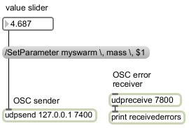
This patch will create a slider, that controls the mass of a swarm called myswarm (make sure the name corresponds to your ISO-internal swarm name!). There are a couple of things worth pointing out here: There is no actual mention of OSC in the patch; you simply send the messages to a UDP port and assume that the receiver will interpret the data received as OSC - no safety nets involved :). Notice how all commata in the OSC messages need to be "escaped" ( "," becomes "\,") because Max/MSP would otherwise interprete the message as a list delimited by commata. This is a Max/MSP specific restriction! Also we have defined different ports for sending OSC messages and receiving error reports. In case of a 3D-parameter, you patch will have to combine the three separate sliders into one list:
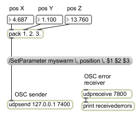
Naturally these two ports need to correspond to your receiver/sender inside of ISO. For simplicity's sake, we have combined the OSC receiver and sender into one object, called "OSCControl":
simulation.com().createOSCControl( 7400, "127.0.0.1", 7800 );
//receiving port, error msg receiver's IP adress, error msg sending port
In both the Max/MSP patch and the example code snippet, we are sending to the IP adress 127.0.0.1 which is to say, we are sending to the localhost. Don't use the same port for sending OSC messages and passing back error messsages - also make sure that the ports are unused by other network applications. If necessary refer to this list of UDP and TCP ports commonly used. And last but not least a little no-brainer: Make sure the port numbers match (Max/MSP sends to a ISO flock port on which the flock has a OSC receiver registered)!
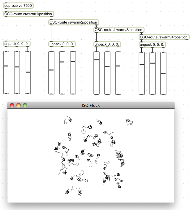
Also a very common scenario would be the usage of flock-generated data insider Max/MSP. For this task, we recommend you download and install CNMATS osc-route object (download link scroll to the "osc-route" object in the list). Extract the downloaded zip and place the .mxo file in "max-externals" and the .help file in "max-help". Then (re)start Max/MSP. Next you can build a patch that listens on a certain port for OSC data from the flock. In our examples, we usually use the port 7500 for outbound OSC data from the flock. The freshly installed osc-route object will try to match the incomming OSC match exactly to its own parameter (e.g. "/swarm/1/position" which translates into: a swarm called "swarm", agent #1, parameter "position"). Matching OSC messages are striped of their header ("/swarm/1/position") and the rest of the message is output through its first outlet - if the message doesn't match, it's output un-altered through the second outlet. That's why in our example several osc-route objects are connected in a waterfall-style manner.
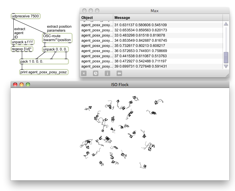
In case you would like to be a little less specific, you can also use "*" for any of the header arguments. For example "/swarm/*/position" would translate into: Swarm called "swarm", ANY agent, parameter "position".
In case you have A LOT of agents, you can use the following method to extract the ID from the OSC message (using regexp).
Before you start using python to access your flock (send settings and retrieve flock data), you'll have to install pyliblo (at the date of writing this documentation: pyliblo-0.9.0). The according tar.gz file can be downloaded here. Unpack it and navigate to the uncompressed directory using the Terminal. Install pyliblo by entering "./setup.py build" and then "sudo ./setup.py install". The code bellow has been tested with OS X 10.6 Snow Leopard and Python 2.6.1.
Please download our example code iso_flock.py, which can be executed using the Terminal statement
python iso_flock.py
The code essentially consists of two classes for receiving data from your flock and a series of statements inside the main() method that will initialize your flock according to your needs. The class ErrorServer will receive any errors ISOFlock encounters while trying to interpret your python-sent instructions and the class FlockReiver will receive the remaining messages. What exactly these messages are, is defined by /RegisterParameter in your python script or directly inside your ISOFlock C++ code. In our example, we are merely interested in the position of the agents and will thus register the parameter "position" with the FlockDataSender, which in turn is created by a /AddSender statement.
send(target, "/AddSender", "FlockDataSender", ",", "127.0.0.1", ",",
    7500, ",", "UDP", ",", "OSC")
send(target, "/RegisterParameter", "FlockDataSender", ",", "swarm", ",",
    "position", ",", -5.0, -5.0, -5.0, ",", 5.0, 5.0, 5.0)
target refers here to the receiving network socket on port 7400. This is accomplished by the instruction "target = Adress(7400)" which assumes you are targeting the localhost - if your python OSC control script and ISOFlock don't reside on the same computer, you will have to change this to "target = Address("x.x.x.x",7400)", where x.x.x.x is the IP adress of the computer with ISOFlock running on it. /AddSender and /RegisterParameter are ISOFlock-specific OSC commands it is able to interpret (you will see many more of these throughout the main() method. FlockDataSender is the flock-internal name for the data sender back to the python class FlockReceiver. "," is the delimiter used and "127.0.0.1" and "7500" are of course the IP address and port number ISOFlock should send their messages to. "UDP" and "OSC" are the only types of messages currently supported with ISOFlock. "swarm" is the name of the swarm from which you are expecting the messages from ISOFlock to your python FlockReceiver class and "position" the name of the parameter of interest. The next two triplets are the spacial boundaries for your flock messages. This works exactly like the upperBoundary and lowerBoundary explained in the figure "MIN_BOUNDS and MAX_BOUNDS" in the figure at the start of this tutorial page.
In a lot of these send(target, ...) statements you will see both commata and commata within double quotes. The later is actually an argument of your OSC statement and will be used by ISO Flock to dissect the message into parsable bits. Don't confuse the two or ISOFlock is likely to get a bad hiccup and will complain through your python ErrorServer. Furthermore all of these send() statements are perfectly in alignment with the c++ statements used to setup a swarm, space, agent, behavior and so on. An example:
setting up a swarm space in C++:
simulation.space().addSpace( new space::Space("posSpace", new space::ANNAlg(3) ) );
setting up a swarm space in Python:
send(target, "/AddSpace", "posSpace", ",", "ANN", ",", 3)
For a walkthrough of these setup instructions, please refer to the "Code Samples" tutorial page.